

This is a guest post by Hemalatha Katari, Solution Architect at Accenture, in partnership with AWS Partner Solutions Architect Rohit Satyanarayana.
In this post, we discuss how to use AWS Data Migration Service (AWS DMS) to migrate your database while maintaining strict network segregation and network security requirements. We recently used this solution with a customer who had strict network security requirements.
When regulated industries and security conscious customers must migrate their on-premises database to the cloud, they have to comply with strict network security and isolation requirements. Such customers do not allow any connections to the database except from within their internal networks application tier. Customers will have strict security compliance and zoning requirements on the AWS Cloud and on premises. Customers with strict requirements usually implement a strict three-tier zoned network:
DMZ (Demilitarized Zone) tier
Application tier
Database tier
Access to data in the database tier in each network is possible only from the application tier in the same network. Incoming and outgoing traffic to and from any external network must be through the DMZ tier in the same network only. The strict network segmentation can be implemented in AWS utilizing subnets with proper route tables for each tier, as illustrated in the following diagram.
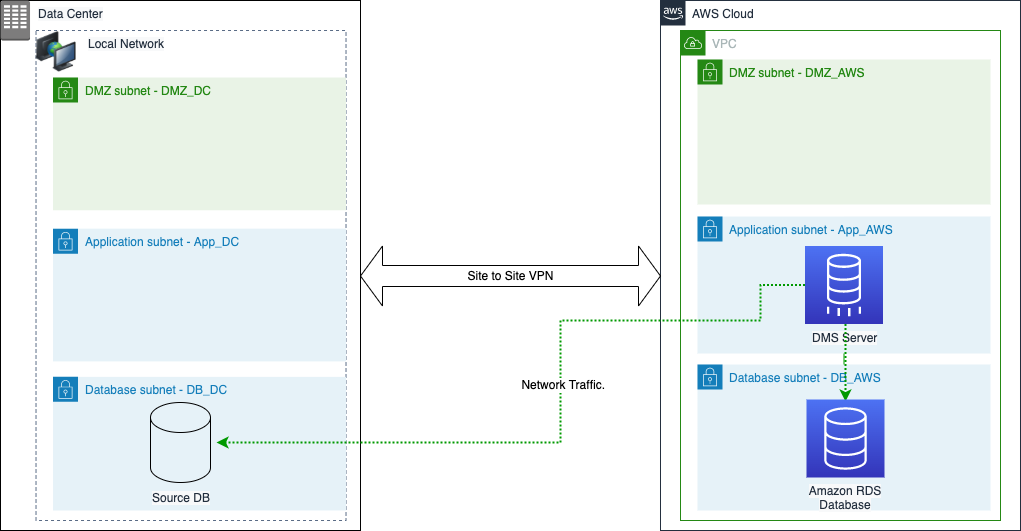
Our customer wanted AWS DMS to be compliant with these requirements. If we consider Amazon Virtual Private Cloud (Amazon VPC) as the target network (labeled as AWS) and the local data center as the source network (labeled as DC), the network traffic flow initiates from the AWS DMS instance in the target network to the source database in the local data center. The network flow would look like the following diagram.
AWS DMS needs direct ODBC connectivity from its replication instance to both source and target databases. Traditional AWS DMS implementations look similar to the following diagram from a network connectivity perspective.
Let’s assume that the AWS DMS replication instance resides in the application tier (subnet App_AWS) in the target network. In this scenario of multi-layered network segments, AWS DMS doesn’t have any components to install in the application tier (subnet App_DC) in the source network. If you installed the AWS DMS replication instance in App_DC instead, then there aren’t any components to install in the target network subnet App_AWS.
This implementation would violate our customer’s network security requirements in two ways:
The source database in the local data center subnet DB_DC is accessed from a different network directly. This is against the network security policy that mandates all incoming traffic into a database must directly come from the application tier subnet App_DC. If the location of the replication instance is changed to local data center, the rule is still violated in the VPC network.
Outgoing traffic from the VPC leaves the network directly from the application subnet App_AWS and enters directly into the database tier DB_DC in the data center network. This isn’t allowed because all traffic flowing from one isolated network to another network must always leave and enter from the DMZ layer; no direct links from the other layers within the network are allowed.
In the next section, we provide a detailed solution to meet the above security requirements that uses NGINX Open Source as a transparent reverse proxy to manage the network security requirements. We show how to provide end-to-end network security and perform some performance benchmarks to understand the impact of the reverse proxy layers on the overall performance of AWS DMS.
Solution overview
To use AWS DMS as the migration tool, we propose a network architecture that is compliant with the customer’s security requirements. AWS DMS supports migrating data across two VPCs or between a VPC and the customer DC using AWS Direct Connect or VPN connections. For more information about standard network configurations for AWS DMS, see Setting up a network for a replication instance. We propose a solution based on Nginx as a TCP streaming proxy to change the way the AWS DMS replication instance connects to the source endpoint.
We configure AWS DMS with a Nginx proxy as the source database. When AWS DMS sends a request to the source endpoint Nginx server, the Nginx proxy relays the request to the upstream server. When a response is received from the upstream server, Nginx relays that response to the AWS DMS replication instance to facilitate the database migration from on-premises to the AWS Cloud.
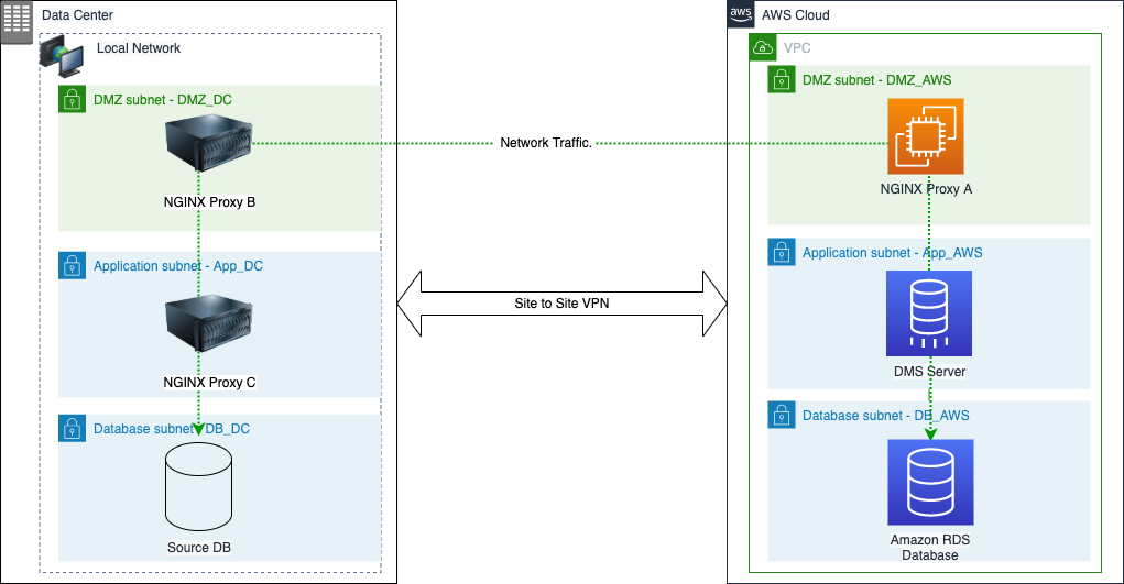
We implement a chain of proxy servers running in both source and target networks to create a network architecture that is compliant with the network security requirements, as shown in the following diagram.
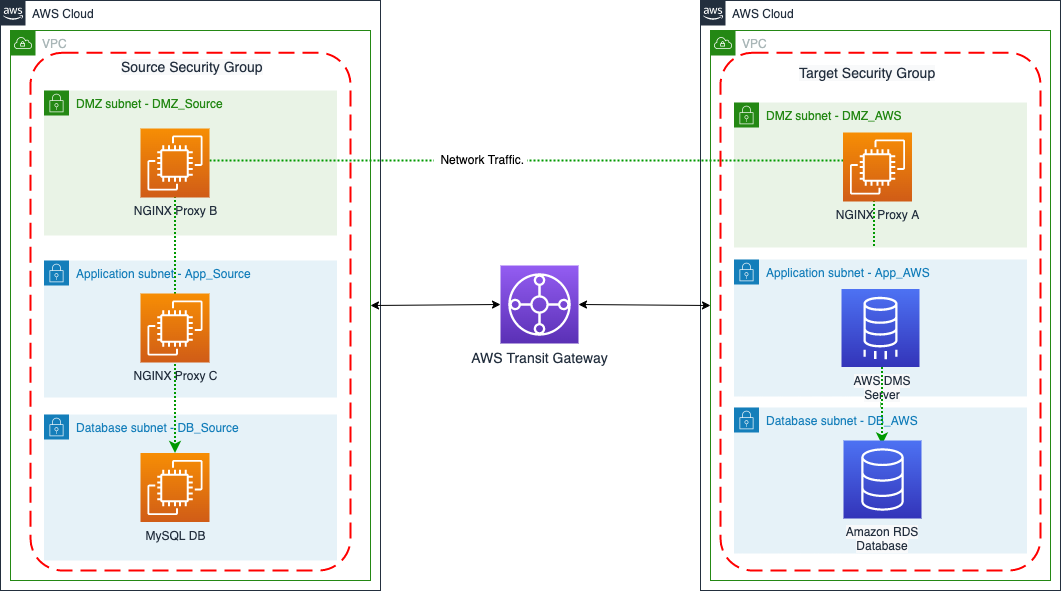
For this post, we utilize two different VPCs to represent source and target networks. The source environment that was originally the local data center network is simulated by a different VPC in the AWS environment. There are two VPCs in this implementation: the source VPC and target VPC, with different CIDR ranges. The two VPCs are connected via AWS Transit Gateway. To keep things straightforward, we use only one security group per VPC. The following diagram illustrates the network architecture.
In a real-life production network, the local data center is connected to the AWS Cloud via either a Direct Connect connection or using an AWS VPN site-to-site VPN link. We strongly recommend using individual security groups for each of the network segments in production workloads. In a production environment, you can design the security groups as follows as an example: Create a security group that is associated with each of the subnets. So the DMZ_AWS subnet will have the security group, DMZ_AWS_SG. The App_AWS subnet will have a security group called App_AWS_SG. And the DB_AWS subnet will have a security group called DB_AWS_SG associated with it. To secure traffic flow, you then create traffic flow rules as follows:
Type
Protocol
Port Range
Source
Description
In Security Group – DMZ_AWS_SG
MySQL/Aurora
TCP
3306
DMZ_Source_SG or IP address of Nginx server in DMZ_Source network
Allow traffic from DMZ_AWS network based interfaces for MySQL only.
In Security Group – App_AWS_SG
MySQL/Aurora
TCP
3306
DMZ_AWS_SG Security Group
Allow traffic from DMZ_AWS network based interfaces for MySQL only.
In Security Group – DB_AWS_SG
MySQL/Aurora
TCP
3306
App_AWS_SG Security Group
Allow traffic from App_AWS network based interfaces for MySQL only.
You can setup a similar set of security groups for your source network as well, if you are migrating from a different AWS account.
Let’s now explore each of the component layers and the required configurations in detail, starting with the VPC setup.
VPC setup
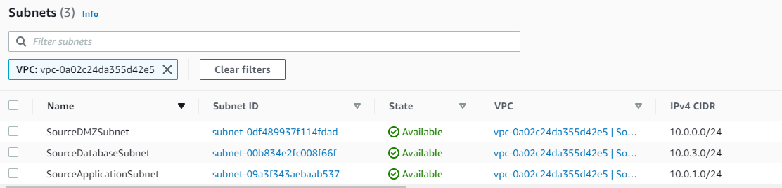
We created two VPCs to represent the source and target environment with different CIDR ranges, as shown in the following screenshot.
You establish connectivity between the two VPCs by setting up an AWS Transit Gateway and peering both the VPCs with the AWS Transit Gateway.
Source VPC
The source VPC has three subnets to represent the three-tier model of the customer’s network. Each tier consists of one subnet, as shown in the following screenshot. The route table associated with the DMZ subnet allows traffic to egress to other VPCs via the AWS Transit Gateway. The route table associated with the application tier only allows traffic to either flow to the DMZ or database subnets or to machines within the application subnet. Similarly, the database subnet associated with the route table ensures traffic from the subnet can only be routed to machines within the same subnet or the application subnet. This simulates the strict three-tier network isolated segments from a traffic routing point of view.
Target VPC
The target VPC in this implementation represents the actual AWS target network that hosts the AWS DMS replication instance and target Amazon Relation Database Service (Amazon RDS) instance resides in. In this VPC, we have two subnets per tier with identical route tables. This is because the AWS DMS replication subnet group and RDS subnet group both need at least two subnets from two different Availability Zones for high availability configuration.
Only the two subnets in the DMZ tier have a route to the other VPC via a AWS Transit Gateway. This makes sure there is no direct connectivity from the application tier or database tier in the target VPC to the source VPC. The route table associated with the database tier only allows traffic to the application tier or systems within the database tier. Similarly, the route table associated with the application tier only allows traffic to either the DMZ tier or the database tier or systems within the application tier.
Security groups
For this post, we used a single security group across all the subnets in a given VPC. In a real-life production scenario, we recommend implementing multiple security groups—at least one per subnet—to make sure that network traffic isolation can be achieved easily without needing to manage complex and large security group configurations.
Every security group contains inbound rules and outbound rules for managing ingress and egress traffic access control from the subnet. For this post, we use permissive rules to allow all traffic across the two VPCs in both inbound and outbound directions. The outbound rules also allow for HTTP and HTTPS traffic.
In a production deployment, we recommend using specific rules to make sure only authorized traffic flows between the different subnet groups from known endpoints and across the two VPCs.
The following screenshot shows the inbound rules for the source security group.
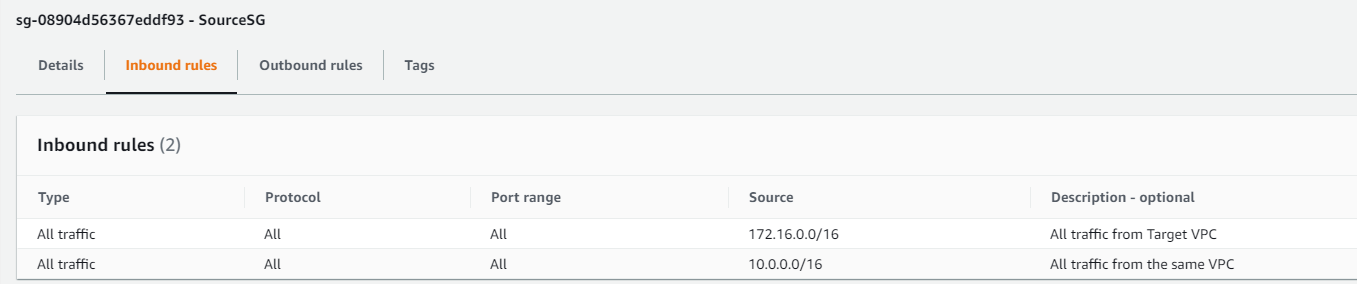
The following screenshot shows the outbound rules for the source security group.
The following screenshot shows the inbound rules for the target security group.
The following screenshot shows the outbound rules for the target security group.
Source database
To simulate the source database in a local data center, we installed MySQL version 5.7 on an Amazon Elastic Compute Cloud (Amazon EC2) instance running Amazon Linux 2, which is launched in the database subnet in the source VPC, as shown in the following screenshot. For installation instructions, refer to Installing MySQL on Linux Using the MySQL Yum Repository.
For instructions on preparing MySQL to act as the source database for AWS DMS, refer to Using a MySQL-compatible database as a source for AWS DMS. As seen in the preceding screenshot, MySQL has the private IP address of 10.0.3.90. We use this IP address in later steps to configure the AWS DMS source database endpoint.
Target RDS instance
Before you create an RDS instance, you must create a DB subnet group from the two subnets created for the database tier in the target VPC, as shown in the following screenshot.
We created an RDS for MySQL instance with the same version as the source database in this DB subnet group in the target VPC, as shown in the following screenshot.
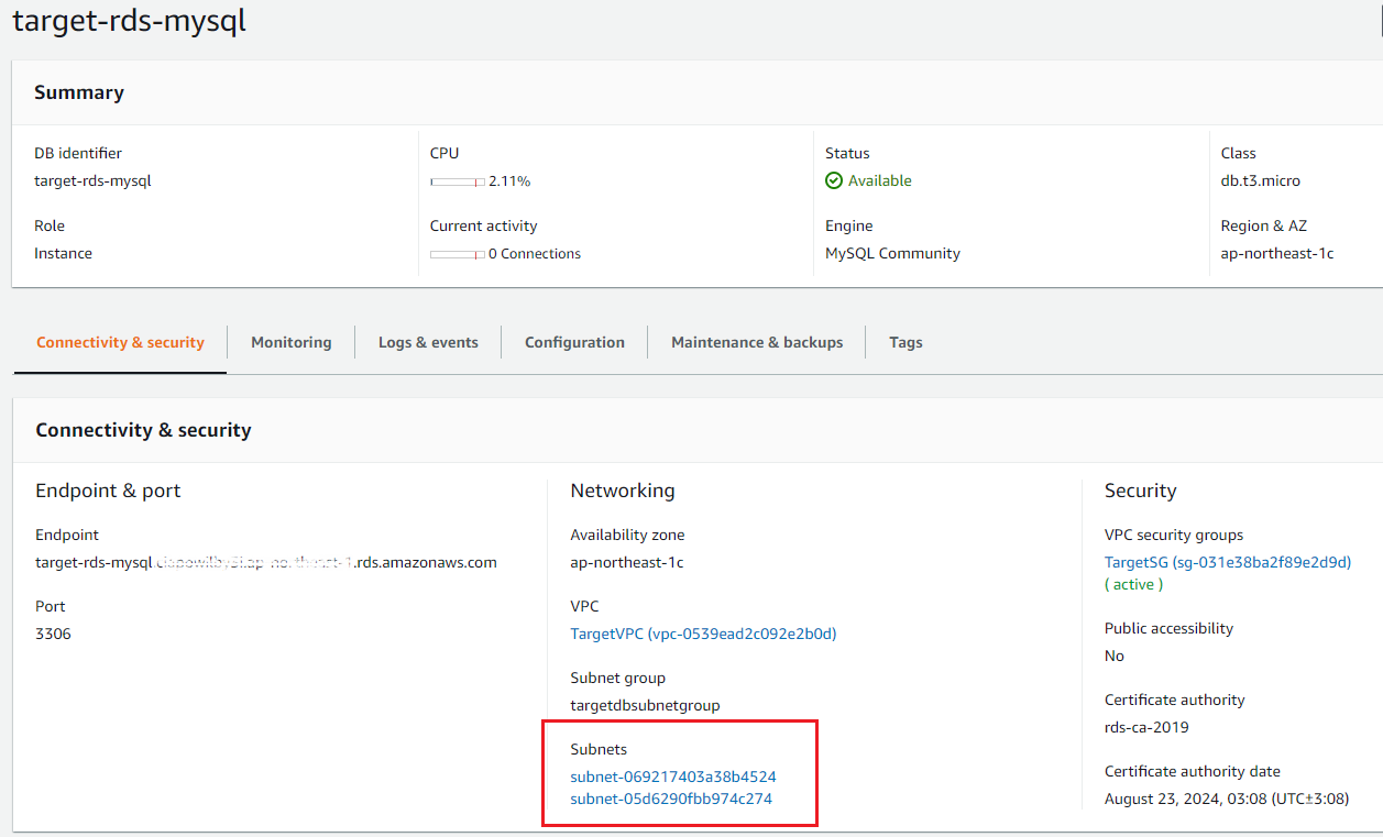
AWS DMS replication instance
Before you create an AWS DMS replication instance, you must create an AWS DMS subnet group from the subnets in the application tier in the target VPC, as shown in the following screenshot. For instructions, see Creating a replication subnet group.
Next, you must create an AWS DMS replication instance within this subnet group. For this post, we use a t3.micro instance with 20 GB of storage. In production scenarios, follow the guidance for choosing your instance type and choosing your instance size to identify the right instance and storage for your replication instance. Our replication instance is a private replication instance that isn’t accessible from the internet.
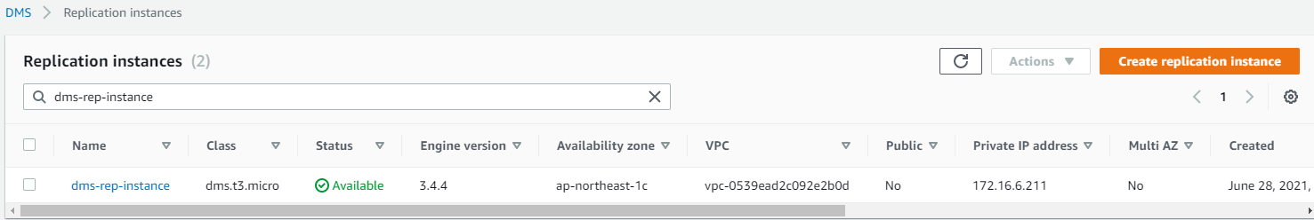
Nginx proxy layers setup and configuration
Before you configure the database endpoints in the AWS DMS replication instance, you must set up the intermediate Nginx proxy layers.
We use EC2 instances to host the Nginx server. The Nginx servers are configured to support proxy chaining via TCP streaming. This enables end-to-end TLS encrypted streams between the AWS DMS replication instance and the DB endpoints without the need for intermediate TLS termination on the Nginx proxy nodes. In our tests, we used the Amazon Linux 2 AMI with t2.medium as the instance type for the Nginx nodes. In a production deployment, the choice of the instance type for the Nginx node depends on the size of the database being replicated, number of daily transactions, expected replication duration, and network bandwidth, and so on.
To install and configure your Nginx instance on Amazon Linux 2 based on EC2 instances, complete the following steps:
Connect to your EC2 instance using a terminal interface and install Nginx.
Update the Nginx config file (located in /etc/nginx/nginx.conf) with the following settings.
In this configuration file, <config> is a name you provide for the configuration, and <server name or IP>:<port> is the DNS server name or IP address that Nginx sends the traffic to.
For this example, we configured Nginx on port 8080, but you can run on any other port.
Refer to the Nginx documentation for more details.
Restart the Nginx service:
You must repeat the preceding steps on each of the Nginx proxy servers in the setup.
NGINX proxy server implementation
For this solution, we deploy three Nginx proxy servers using EC2 instances launched in the following subnets:
Target VPC:
Nginx proxy A: DMZ subnet
Source VPC:
Nginx proxy B: DMZ subnet
Nginx proxy C: application subnet
You must note down the private IP addresses of the Nginx proxy EC2 instances. For our Nginx configuration, the private IP addresses of the servers are as follows:
Nginx Proxy A: 172.16.1.55
Nginx Proxy B: 10.0.0.218
Nginx Proxy C: 10.0.1.167
On all three servers, Nginx is running on port 8080.
Also, the EC2 instance running the source database has the private IP address 10.0.3.90, and MySQL is running on default port 3306.
Therefore, the traffic flow from the AWS DMS replication instance to the source database chains through Nginx proxies, as shown in the following figure.
In this chain, each proxy forwards network traffic to the next block via a TCP stream. The following code is the Nginx configuration file for each proxy server:
Nginx proxy A:
Nginx proxy B:
Nginx proxy C:
At this point, the configuration of the Nginx proxy chain is complete. We can now configure the AWS DMS replication instance.
AWS DMS replication endpoints
The next step in configuring the AWS DMS replication endpoints is to point it at the source and target databases.
Source endpoint
The AWS DMS replication instance points to Nginx proxy A (the server with the IP address 172.16.1.55 and port 8080). The Nginx proxy chain implementation forwards traffic to the next step in the chain until it reaches the source database. To configure an endpoint in AWS DMS, refer to Creating source and target endpoints. The following screenshot shows the configuration for the source endpoint based on our setup.
The endpoint should now be successfully created, and you can run a successful endpoint connection test as shown in the following screenshot.
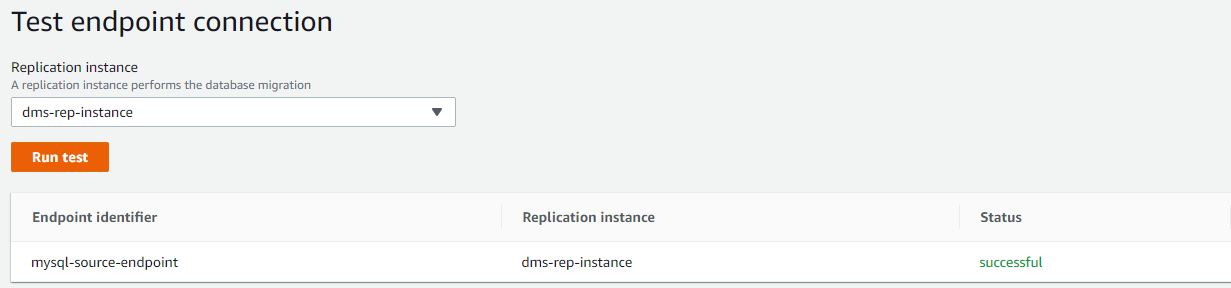
Target endpoint
You create the target endpoint using the database endpoint and port because the AWS DMS replication instance and target RDS instance are located in the same VPC, but different subnets. The following screenshot shows an overview of the target endpoint configuration.
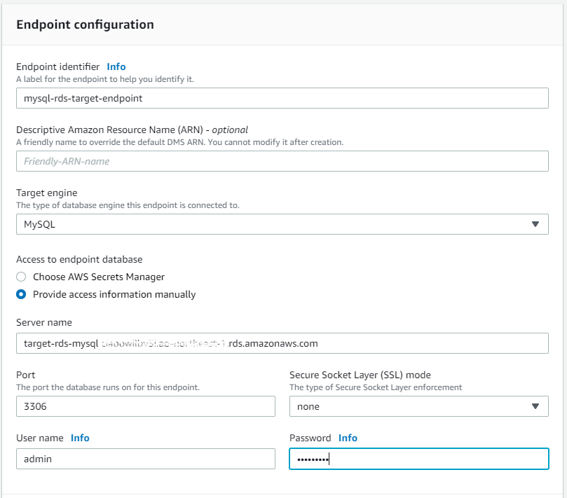
After you create the target endpoint, you should make sure that the AWS DMS replication instance can successfully connect to the target RDS instance by running an endpoint connection test, as shown in the following screenshot.
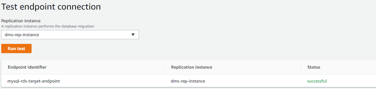
AWS DMS migration task
Now that you have configured the source and target endpoints, you can create an AWS DMS task to perform a successful migration via the Nginx proxy chain implementation.
Set up source and target databases
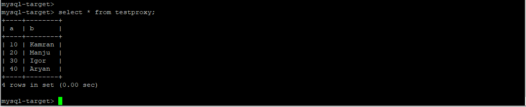
Connect to the MySQL source database via a remote shell. On the source MySQL database running on Amazon EC2, create a sample database called testdms with a simple table named testproxy containing a few rows, using the following commands:
Log in to the MySQL database:
Create a test database:
Make the new database the active database:
Create a table:
Insert three rows into the table:
List all the records in the new table:
The following screenshot shows the series of commands and their outputs.
If we connect to the target RDS instance via a remote shell and try to list the contents of the RDS instance using the show databases; command, it responds that the testdms database doesn’t exist in the RDS instance.
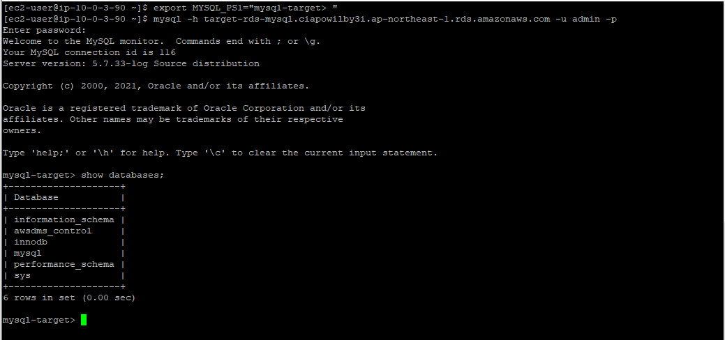
Create an AWS DMS task
Now you must create an AWS DMS task to migrate data from the source (simulated on-premises) database to the target database. You can create a task that does a full load from the source database into the target server as well as handles change data capture (CDC) to manage replication of data that has been inserted, updated, and deleted after the full load. This makes sure that the source and target databases remain in sync. To configure an AWS DMS task, see Creating a task. The following screenshot shows the overview details for the AWS DMS task.
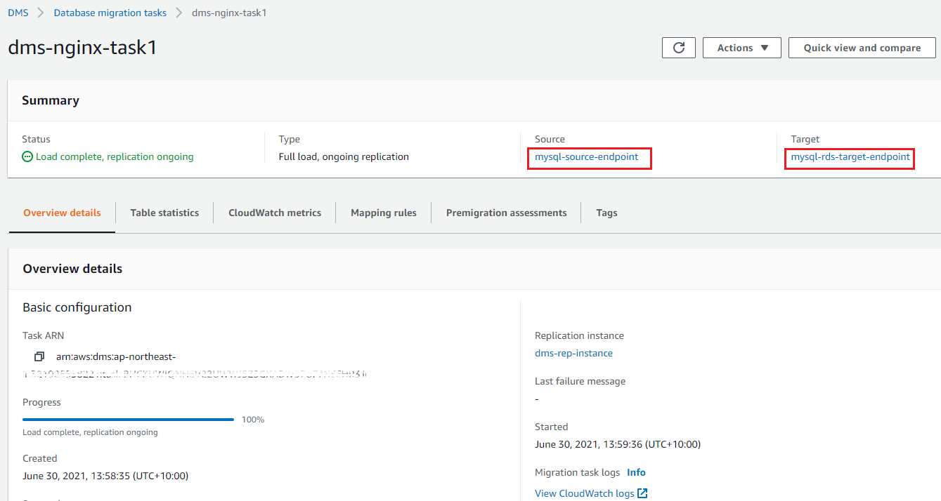
While you’re creating the AWS DMS task, you must define a mapping rule that maps the entities in the source database you want to migrate to the target database. The following screenshot shows how to set up the mapping rule for our scenario.
Mapping rules can be defined using JSON based syntax. In the example screenshot, the mapping rule is defined as follows:
The above rule basically defines that source objects (“object-locator”) are in the database (“schema-name”) called “testdms”. And from the source database, you are looking for objects (“table-name”) with a name that meet the criteria “%” – a wildcard indicating all objects. The rule will select all the objects that matches the criteria and perform the action “include” based on the value of the (“rule-action”) field. For a detailed understanding on how to define mapping rules in JSON, refer to Specifying table selection and transformations rules using JSON.
After you create the AWS DMS task, you can choose to run the task automatically or manually start it from the AWS DMS Dashboard page. The task runs and completes the full load replication from the source to destination database. To verify the successful replication, you can open a remote shell to the target RDS instance and use the following commands to verify the successful completion of the AWS DMS task:
Log in to the MySQL database:
Verify the database was migrated:
Make the new database the active database:
List all the records in the new table:
The following screenshot shows the outputs of these commands and indicates a successful full load migration.
You can also verify that changes made on the source database after full load are successfully replicated using CDC. On the source database, add a new row in the table, as shown in the following screenshot.
After a few seconds, you can connect to the target database to verify that the new row has been transferred to target database.
Using SSL with endpoints
With AWS DMS, you can enable SSL for both the source and target endpoints. For instructions on configuring SSL-enabled endpoints, see Using SSL with AWS Database Migration Service. We tested this solution with TLS-enabled source and target endpoints. We only enabled TLS encryption on the source database endpoint and the target database endpoint. This makes sure that the connection is end-to-end encrypted and a malicious user with access to the intermediate proxies can’t intercept any of the network traffic. The following figure illustrates the resulting configuration with SSL termination.
Performance considerations
In one of our tests, we migrated a 2 TB database to test the performance impact of instance size. We observed there was no significant spike on CPU usage on any of the Nginx instances, but there was a spike on the Network-In and Network-Out metrics on all three instances, as shown in the following screenshot.
Based on this observation, CPUUtilization was less than 2% when the task was running. But the Network-In and Network-Out metrics indicate high network throughout requirements on Nginx servers. For very large or dynamic datasets, we recommend using EC2 instances that are optimized for network throughput for the proxy servers. This can reduce the impact of the multiple Nginx proxy chain on the overall AWS DMS task throughput.
We also did a comparative test between using directly connected database endpoints to AWS DMS vs. endpoints that are connected via a network of proxies. We wanted to identify the resulting increased latency and impact to the AWS DMS task completion introduced through the additional Nginx proxy servers. The following screenshot shows the results of the comparative tests.
We ran the test using the same dataset, source database, and target database. The only variations in the two AWS DMS tasks were how was the source database connected to the AWS DMS replication instance—direct vs. a layer of three Nginx proxies. For the scenario with a direct connection between an AWS DMS replication instance and the source database, the entire task completed within 18:44 minutes. For the scenario where the source database was connected to the AWS DMS replication instance via a chain of proxies, the task took 20:5 minutes. The addition of three Nginx proxies into the replication traffic flow increased the latency of the AWS DMS task effectively by 13.5%.
Although neither of these tests are completely scientific in their approach to benchmarking performance numbers for comparison purposes, you can conclude that careful selection of the EC2 instances for Nginx proxies is needed. You must select instance types that will provide sufficient network bandwidth and resources for the AWS DMS replication task to complete with as low a latency as possible based on the nature of the databases you are replicating.
Cleanup
If you followed along the example setup, then you should clean up any resources you created to avoid additional charges in the long run. To perform a cleanup of the resources, you need to:
Delete the DMS Task definition
Delete the DMS Source and Target endpoint definitions
Delete the DMS replication instance
Terminate the different EC2 instances for Nginx proxies and source DB server
Delete the Amazon RDS target database instance
Conclusion
AWS DMS is a viable and easy-to-implement database migration solution for both homogenous and heterogenous databases from on premises to the AWS Cloud, even with strict network security and segregation requirements. A high-performance proxy server like Nginx can help meet your network isolation and security requirements. Although this solution introduces additional latency into the replication process, you can shorten the delays by selecting the appropriate instances for the intermediate Nginx proxies to maximize their network performance. You can also scale Nginx proxy performance by setting up the open-source proxy server in a high availability, load balanced architecture. This can drive down the latency introduced by the proxy layers even more.
To learn more about how to configure an Nginx open-source server for high availability and load balancing, see How to Set up Nginx High Availability with Pacemaker, Corosync, and Crmsh on Ubuntu 16.04. If you have questions or feedback, please leave a comment for us.
Ready to get started? The AABG (Accenture AWS Business Group) helps customers accelerate their pace of digital innovation and realize incremental business value from cloud adoption and transformation. Connect with our team at [email protected] to learn how to use AWS Database Migration Service (AWS DMS) in your products and services.
About the Authors
Rohit Satyanarayana is a Partner Solutions Architect at AWS in Singapore and is part of the AWS GSI team working with Accenture globally. His hobbies are reading fantasy and science fiction, watching movies and listening to music.
Hemalatha Katari is a Solution Architect at Accenture. She is part of rapid prototyping team within the Accenture AWS Business Group (AABG). She helps organizations migrate and run their businesses in AWS cloud. She enjoys growing ornamental indoor plants and loves going for long nature trail walks.
Read MoreAWS Database Blog